


Technical Information
13. Connection types of sensor resistances
a. Two wire circuit
The sensor has two connections, at which a two-core cable connection is attached for control. The problem here is that the conductor possesses an electrical natural resistance, which increases the total resistance and thus – depending on the length of the conductor- leads to a more or less excessive measurement result.
In order to compensate for this, the conductor resistance must be determined and entered into the control as a correction size. In practice resistance thermometers with 2 wire switches, due to the fact described, rarely lead to exact measurement results. The natural resistance of the conductor changes also with changed ambient temperature and/or air humidity.
These resistance thermometers therefore are only used for measurements, with which a tolerance of some degrees is insignificant, e.g. with cooling water.
With high ohmic sensor resistances (Pt500, Pt1000) the measuring error is reduced by the factor 5 and/or. 10, so that this - under the described circumstances- leads to somewhat more exact measurement results.
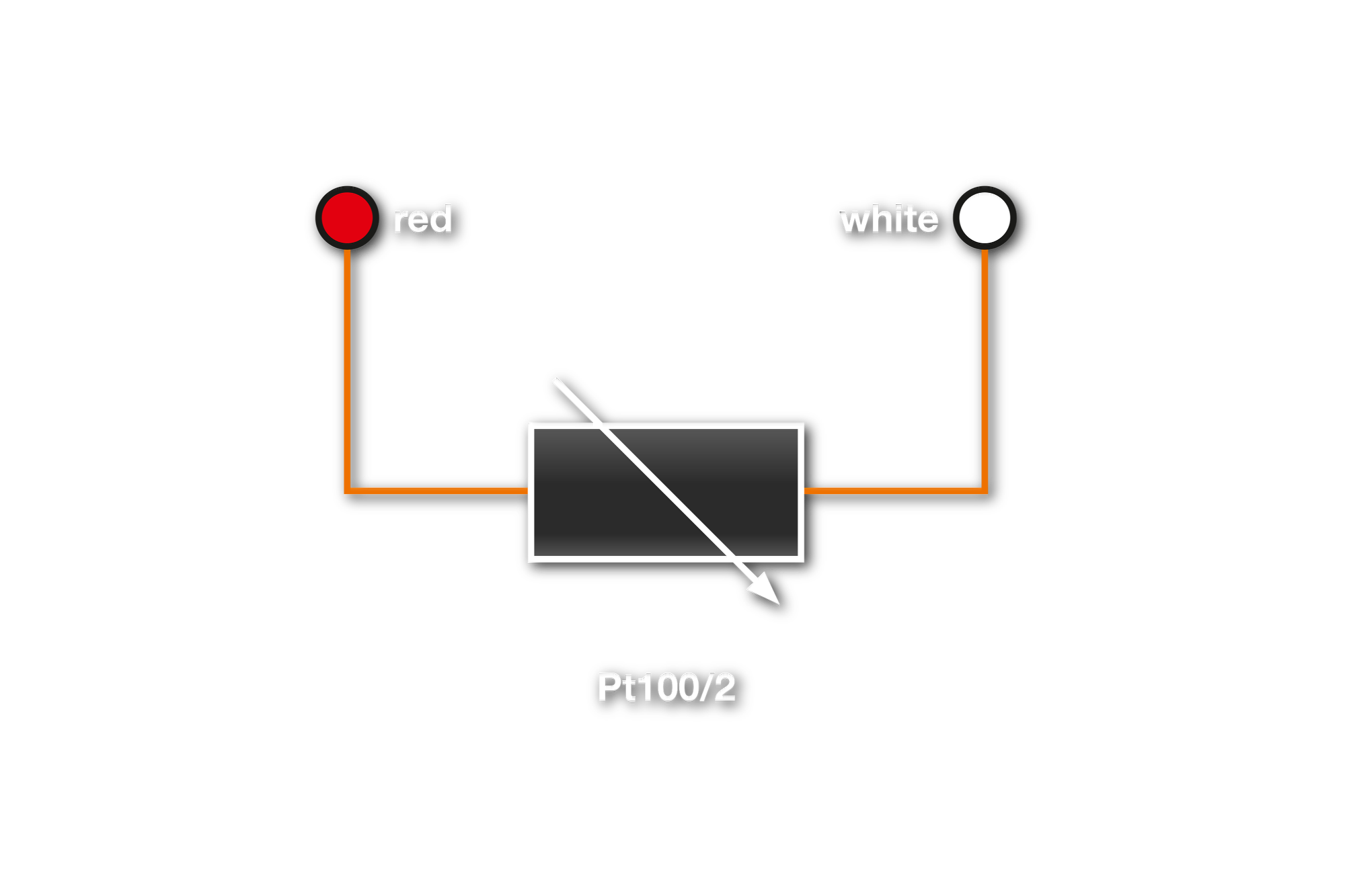
Fig. 1: Two wire circuit
b. Three wire circuit
Resistances in three wire technology function exactly the same as sensors in two wire circuits, however an adjustment of the conductor resistance is not necessary:
An additional wire is connected to a connection of the sensor resistance. Thus a second measuring circle develops, which represents the actual conductor resistance at any time. In the control, this value is now taken off from the value of the measuring circle with resistance and the actual resistance of the sensor is determined.
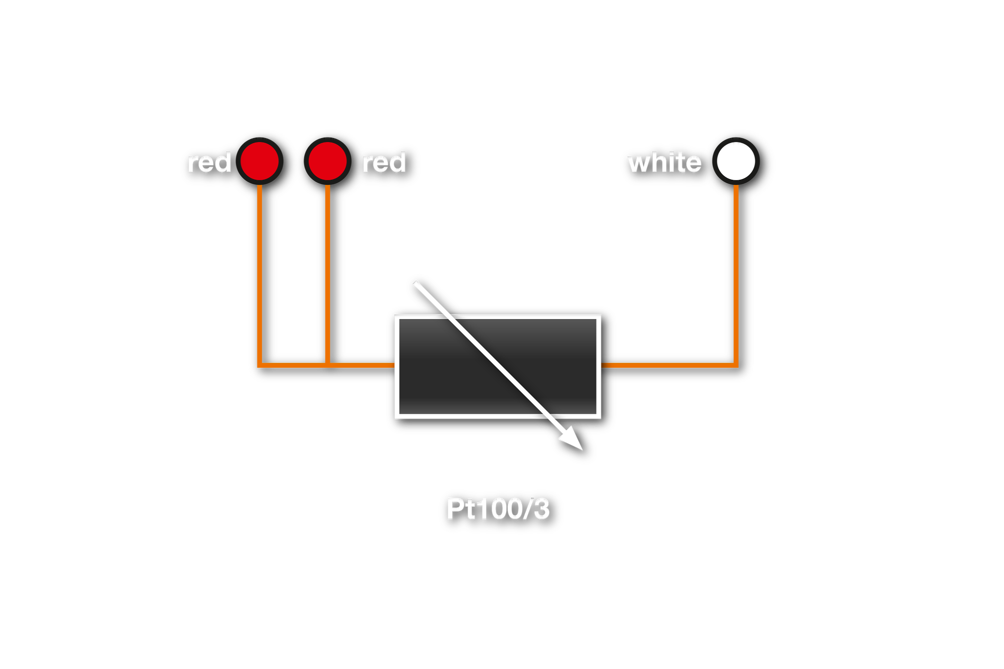
Fig. 2: Three wire circuit
c. Four- wire circuit
in contrast to the three-wire circuit, where only the conductor resistance of one of the two feeds is determined, while with the four wire circuit the resistances of both feeder lines to the resistance are determined. The measurement results are consequently also always accurate if the feeds should have different natural resistances.
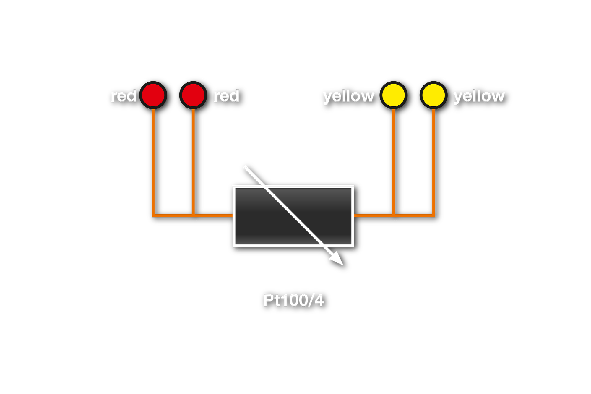
Fig. 3: Four wire circuit
Choose your language
Leave your number and we’ll call you back
Your direct contact to our team
GÜNTHER GmbH
Temperaturmesstechnik
Bauhofstraße 12
D-90571 Schwaig
info@guenther.eu
Tel. +49 (0)911 / 50 69 95-0
Fax +49 (0)911 / 50 69 95-55